
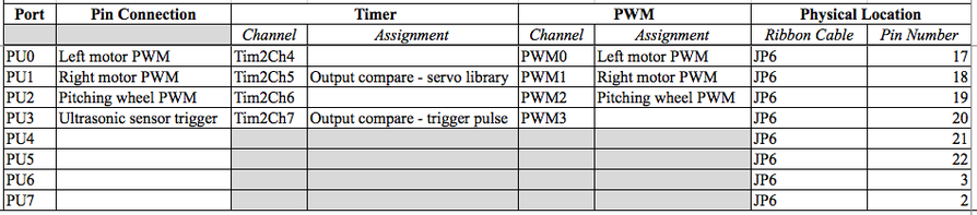
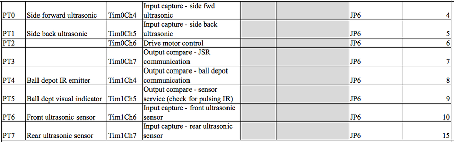
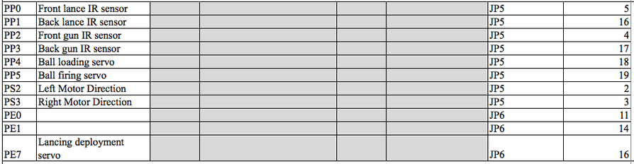
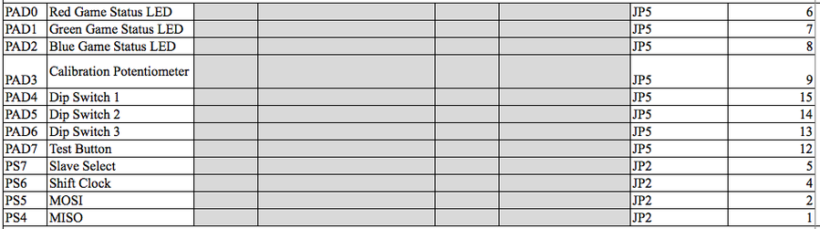
Pinout Diagram for E128
also highlights which Timers and Channels were used and for what function. The Pinout Diagram has multiple sheets, one of which includes our assignemnts for ES_Timers.
also highlights which Timers and Channels were used and for what function. The Pinout Diagram has multiple sheets, one of which includes our assignemnts for ES_Timers.
| team4_e128circuits_pinout.xlsx |
Megatron Key Feature: Sensing
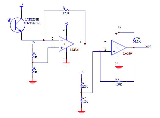
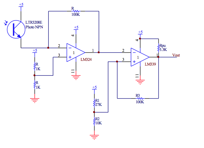
There are 3 infrared sensors the bot uses to sense the opposing knight. These are mounted at the front and rear of the robot. The first stage of each of the circuits is a transresistive circuit, utilizing the LM324 Op Amps. The output is tied to an LM339 comparator such that they reliably output a 5V signal upon sensing the knight head infrared signal. The software is structured such that upon any of these three sensors tripping, the lance servo is put into “lowered” position for 3 seconds, and then raised and placed in “lockout” mode where it cannot be lowered again for one second, per the game rules on lancing.
There are 3 infrared sensors the bot uses to sense the opposing knight. These are mounted at the front and rear of the robot. The first stage of each of the circuits is a transresistive circuit, utilizing the LM324 Op Amps. The output is tied to an LM339 comparator such that they reliably output a 5V signal upon sensing the knight head infrared signal. The software is structured such that upon any of these three sensors tripping, the lance servo is put into “lowered” position for 3 seconds, and then raised and placed in “lockout” mode where it cannot be lowered again for one second, per the game rules on lancing.
|
Goal Sensing Circuit
|
Knight Sensing Circuit (x 2)
|
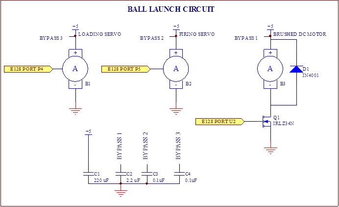
Ball Launching Circuits
The ball launching circuit is comprised of two servo motors and a brushed DC motor. The two servo motors control the gate mechanism for the bot, allowing a single ball at a time to be launched. Both run off a custom made Servo library that was implemented in code. The DC motor was used for the pitching wheel (explained in greater detail in the Mechanicals section) which enabled the bot to shoot balls with greater velocity. The DC motor ran off an IRLZ34N MOSFET and we included a flyback diode to protect the motor from voltage spikes.
The ball launching circuit is comprised of two servo motors and a brushed DC motor. The two servo motors control the gate mechanism for the bot, allowing a single ball at a time to be launched. Both run off a custom made Servo library that was implemented in code. The DC motor was used for the pitching wheel (explained in greater detail in the Mechanicals section) which enabled the bot to shoot balls with greater velocity. The DC motor ran off an IRLZ34N MOSFET and we included a flyback diode to protect the motor from voltage spikes.
Ball Requesting Circuit
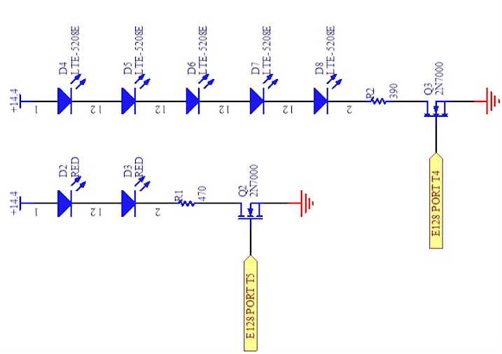
The ball requesting circuit is comprised of 5 IR emitting LED all strung together in series. To effectively communicate with the Ball Depot, an IR emitter has to send 10 pulses each with a 10ms high time (on time) and a 30ms low time (off time). We used 5 emitters (sending the same pulse through each simultaneously) as a precautionary measure so that we weren't relying on a single emitter to line up with the IR reciever on the ball depot.
In addition to the 5 emitters, we had 2 Red LEDs in series on the same circuit which served as a debugging tool - when the red LEDs were on, it was confirmation that the 5 emitters were pulsing.
|
Motor Circuit
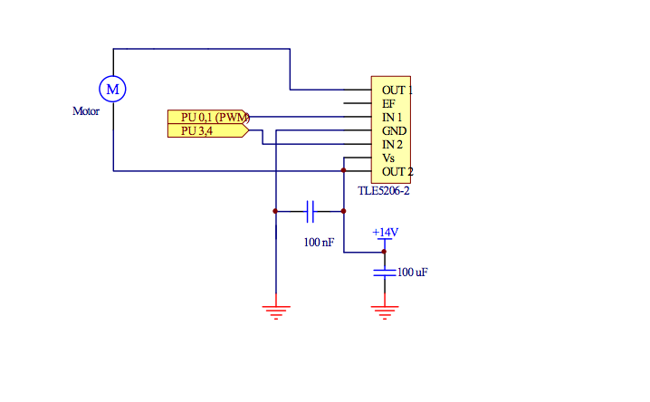
At the crux of the Motor Circuit is the TLE5206-2 H-bridge IC (integrated circuit), a MOSFET-based Hbridge. The R(dsON) for the high side MOSFETs in the circuit are (at max) 800 mOhms. For the low side MOSFETs the R(dsON) is, at max, 1 Ohm.
|
Voltage Regulator
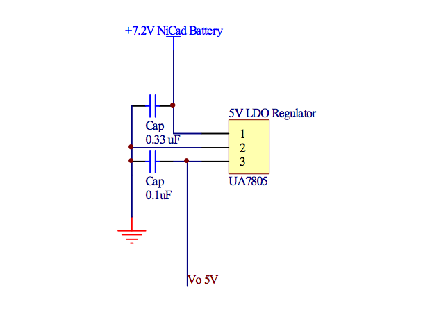
We used a voltage regulator for the power to all of our sensing circuits, which ensured the IC's (integrated circuits) in those circuits would not be receiving more power than they were rated for. This also served as a precaution against any noise issues.
|
|
Ultrasonic Sensors
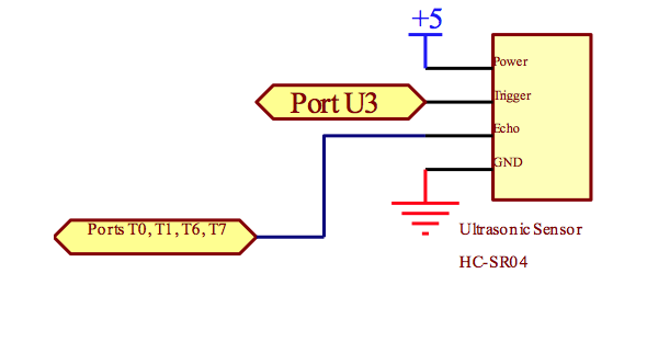
The ultrasonic sensors were used for alignment (with respect to the center wall) to ensure the bot was driving straight. We used four ultrasonic sensors two on the right side of the bot (the side facing the wall), one in the front and one in the back.
As the above schematic indicates, we used the same port (U3) to trigger each of the sensors. The output of each sensor (Echo) was individually tied to a specific port. One sensor was tied to T0, another to T1, etc. Each output had an associated input capture interrupt in code - which was how each echo served as an input in our code. |
Debugging Indicator Circuit

The 3 IR sensing circuits (Knight Sensing and Goal Sensing) and the Ball Depot Communication circuit each had this indicator circuit tied to its output. By having an LED high side with a 2N7000 MOSFET, we had clear indicators as to whether or not the circuit of interest was behaving as expected. The output of the circuit of interest is tied to the gate of MOSFET, so when there's any type of high pulse the MOSFET will turn on, allowing current to flow through the LED,turning it on.
|
